The Schaudt Elektroblock is an all-in-one power distribution, control and battery charging system for Motorhomes & Caravans – predominantly fitted to German built vehicles. Our’s recently started misbehaving on a recent trip to Europe, and while it was sent away and repaired by a specialist after the trip it made me lose some faith in the 20 year old components it is made from!
I started thinking about whether it would be possible to replace the whole unit with a plug-and-play DIY solution (our version – an EBL 4-105 – is not available anymore, and current versions (which wouldn’t be a direct swap anyway) are over £500….)
On reviewing the Schematics and poking about inside the unit it became clear that there is not actually all that much to them, most of the intelligence is in the battery charger bit and by separating out the functions I could use an off-the-shelf battery charger and create a separate power distribution system that plugs straight into our motorhomes wiring.
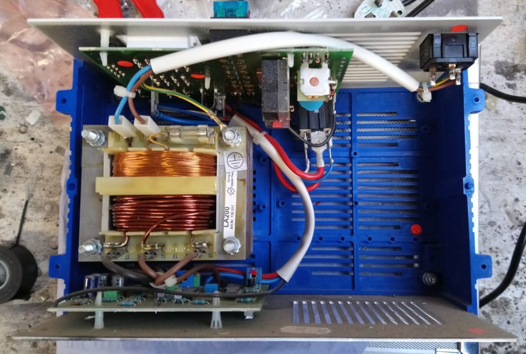
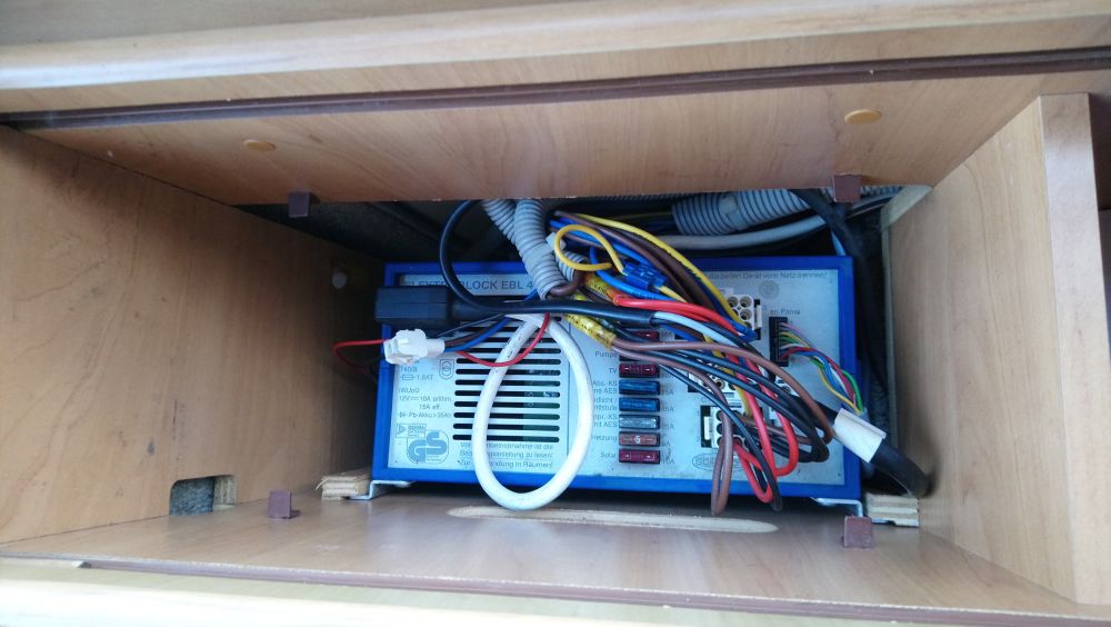
This is the inside of the unit – the large transformer and lower circuit board make up the battery charger, the upper circuit board is the power distribution, fuses, relays etc. The rest of it is fresh air!
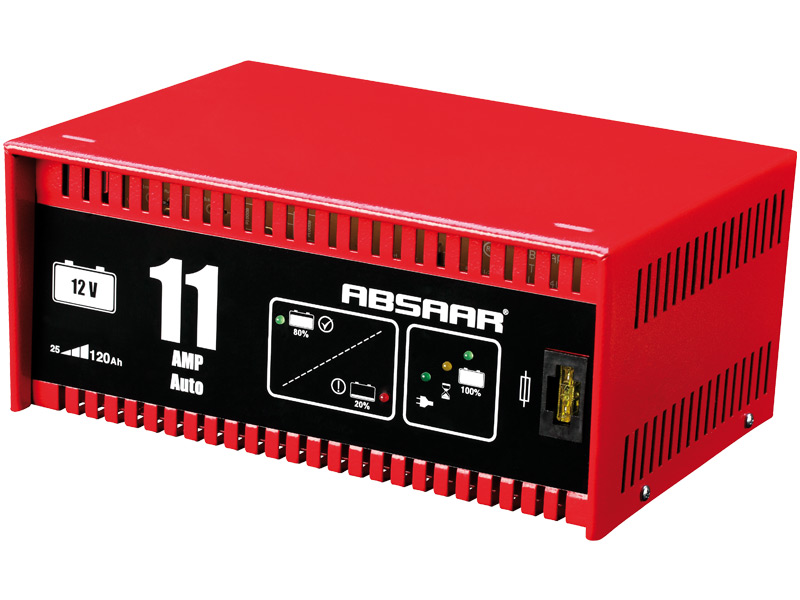
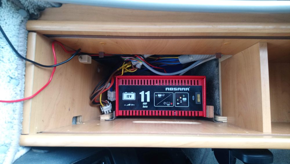
The first step is to select a suitable battery charger that can be left permanently connected to the leisure battery – I selected this 11amp automatic unit from Absaar (similar capability to the 10amp unit in the original Elektroblock)
Note: I ended up not using this particular charger, as it makes an annoying loud buzzing noise when it is operating! – but it’s useful for showing the process I went through in integrating it to the motorhome
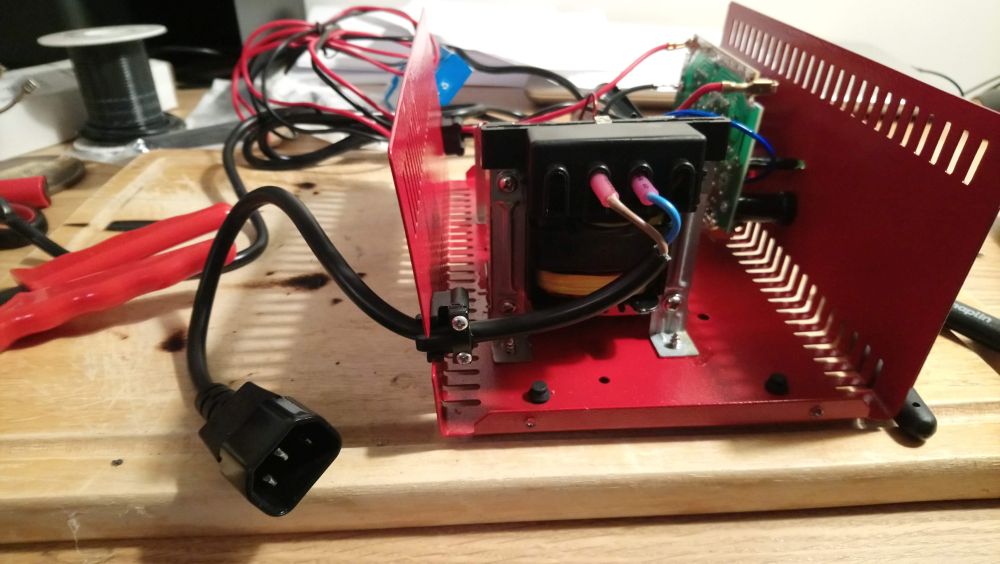
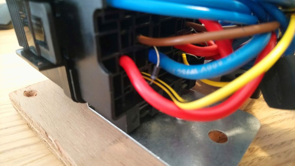
To prepare the mains side of the wiring I replaced the original 3 pin plug lead on the charger with a ‘kettle’ type socket. This allows the motorhome wiring to plug straight in.
This is the Elektroblock in it’s original location inside a cupboard on the right hand side of the cab, the metal angles on the bottom slot in channels in the wood.
Adding some 90 degree metal angles to the sides of the new charger allows it to slot into the exiting channels
Next step was to design a distribution and fusing system to handle the rest of the Elektroblock functions, based on the original schematics for the EBL 4-105. This is the schematic for the new system:-
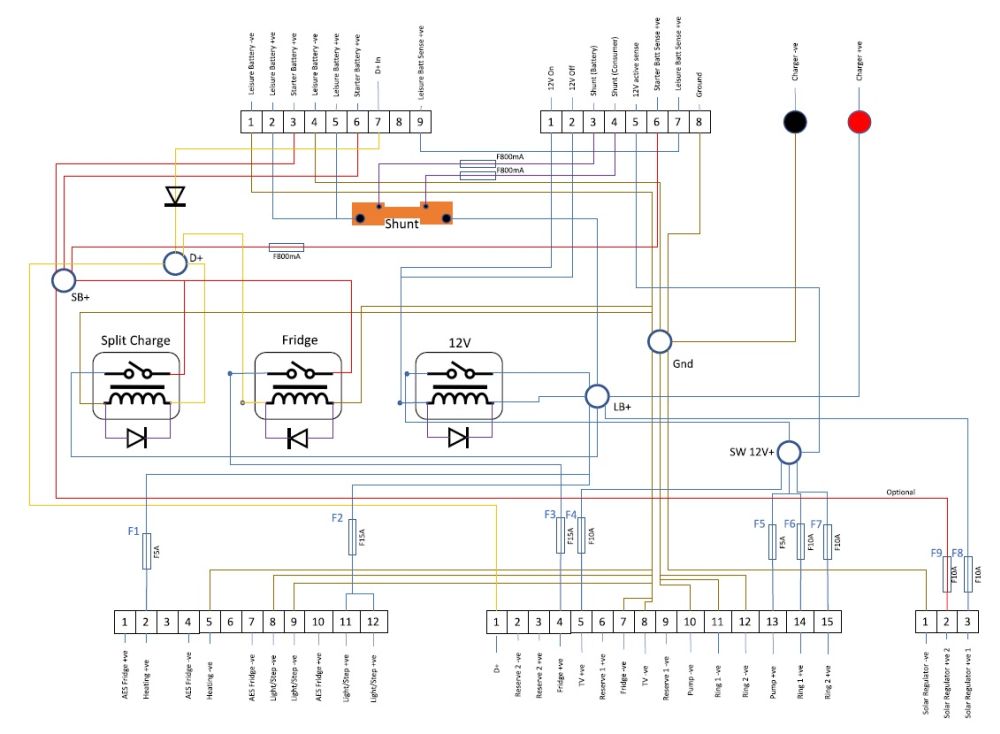
The main functions are as follows:
- Relay for split charge (to charge the leisure batteries when the engine is running)
- Relay for the fridge (to power the fridge from 12V when the engine is running)
- 12V systems relay (to turn the 12V supplies on when switched on from the control panel)
- A shunt to measure the current going in/out of the leisure battery, to drive the ammeter on the control panel
- Fuses to protect all the circuits
- Plugs to connect to the original motorhome wiring (1x input mate-n-lok, 2x output mate-n-lok, 1x solar connection mate-n-lok, 1x 8-way panel connector)
- Connection points for the 12V feed from the charger
- Flyback diodes for the relays, and a diode to prevent the leisure batteries from back-feeding the alternator
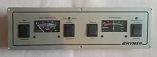
This is the control panel as fitted to the motorhome that interfaces to the Elektroblock. It contains a voltmeter for starter and leisure batteries, an ammeter for current in/out of the leisure batteries, and a switch to turn the 12V circuits on/off
The two relays for the split-charge and fridge are switched from theT alternator D+ terminal, so I used standard automotive 40A relays. To house these I picked up a combined relay/fuse box that holds 2x relay and 8x automotive fuses, and comes complete with all the necessary terminals to wire it up:-
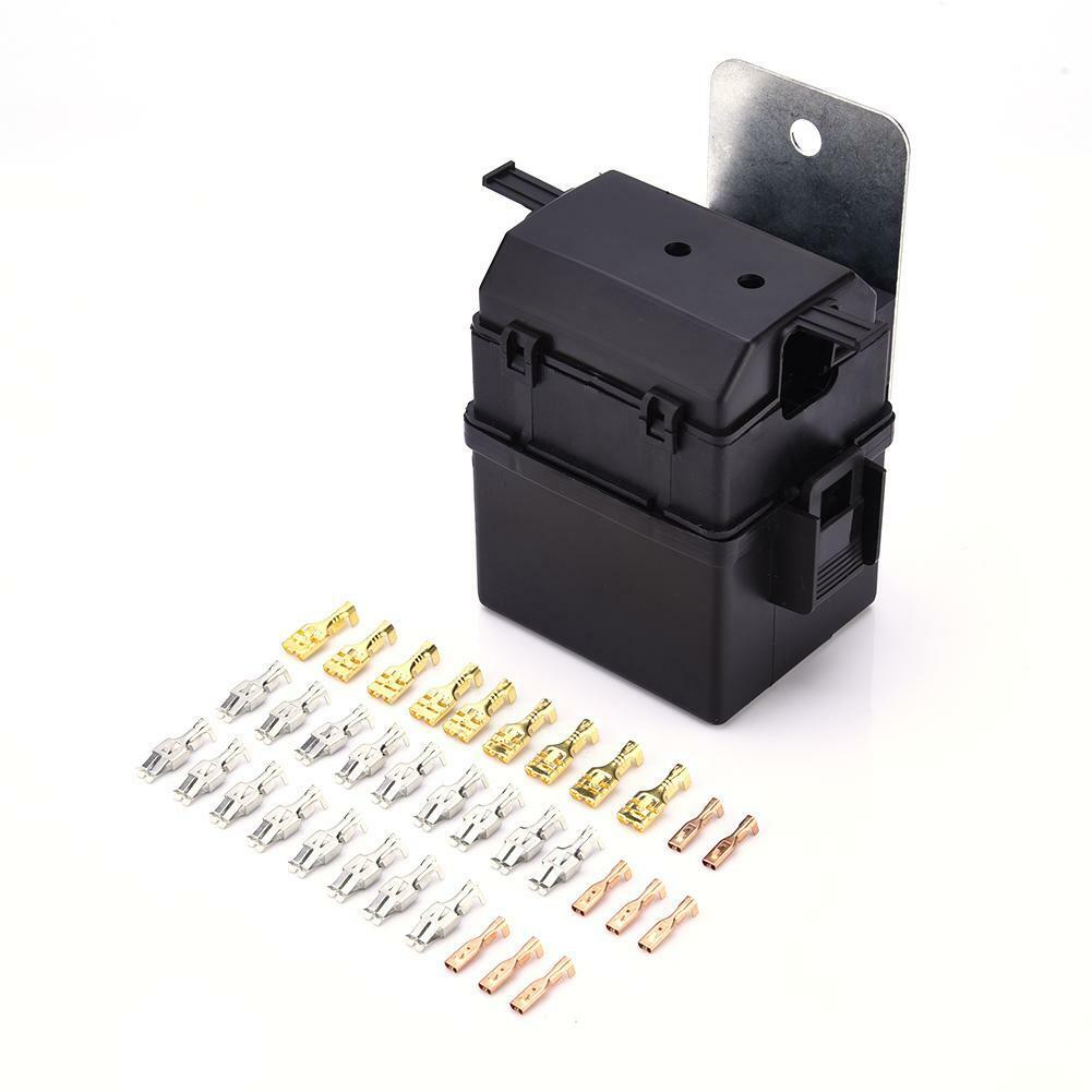
Fuse and relay box, cost just £7.59 delivered
The relay for the switched 12V circuits needs to toggle between on & off when it receives a momentary signal from the control panel, so a more specialised relay is required here. I used a Finder DPST DIN rail mount 12V latching relay. This has the added benefit that it can be actuated manually, so should the control panel/switch/wiring fail, the 12V circuits can still be switched on/off by pressing the button on the front of the relay:-
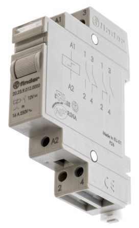
Finder 12V DIN rail mount relay
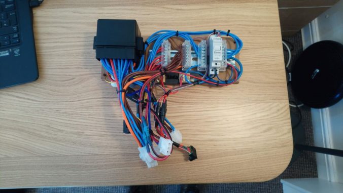
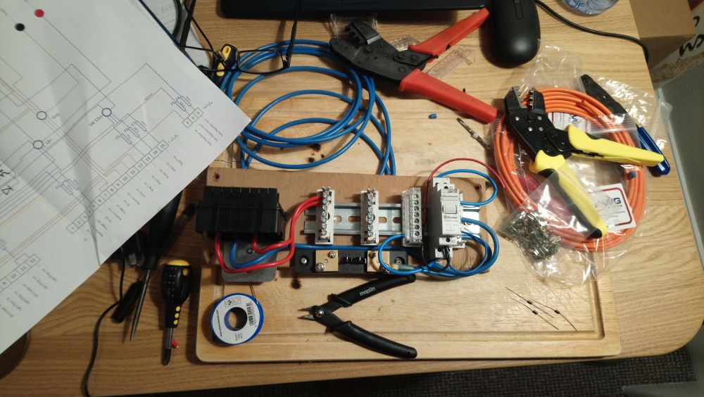
For easy access I opted to mount all the distibution components to a wooden board that will go above the charger unit in the cupboard. The fuse box and shunt are screwed directly to this board, and a din rail is added to hold the Finder relay and some DIN rail mount distribution blocks for the various circuits. Here is the fusebox, finder relay and shunt mounted up and the first bits of wiring connected:-
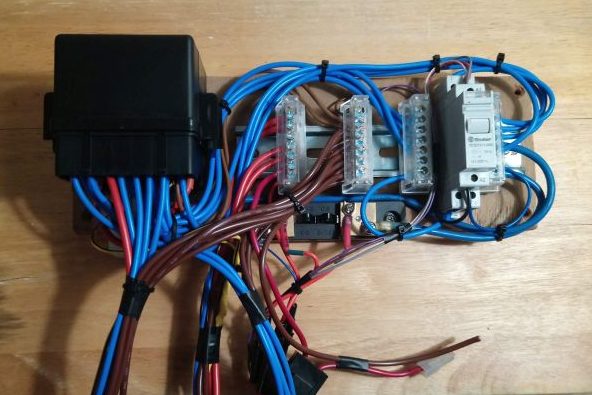
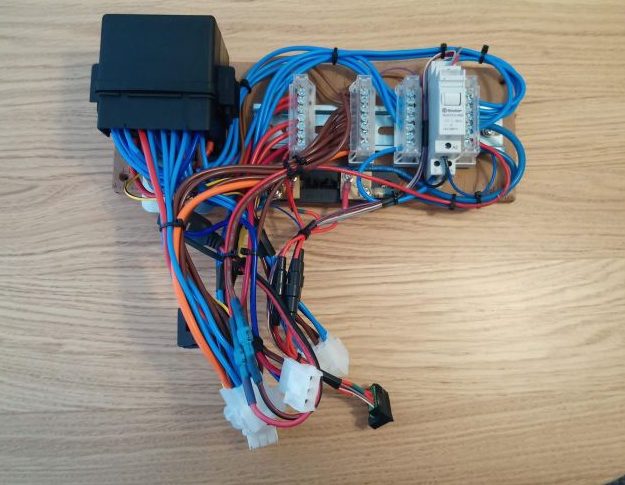
Here is the board with all the wiring added, ready for the plugs to be terminated:-
The flyback diodes for the relays in the fusebox are connected directly to the coil terminals – you can see them here in the fusebox wiring:-
The flyback diode for the finder relay is connected to the coil terminals (top and bottom of the relay) and lay down the left side of the relay itself
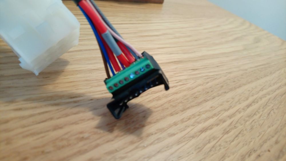
Next job was to start terminating the plugs. For the panel connector I could only find the mating half in a PCB mount version, so I soldered it onto a piece of prototyping board and added an 8-way PCB mount screw terminal connector to wire it up:-
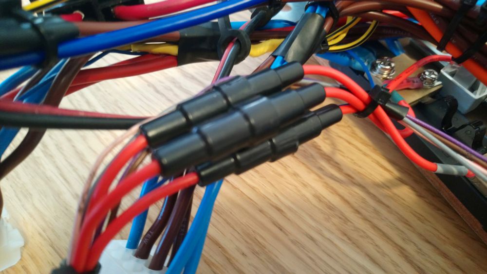
In the original motorhome wiring the starter battery sense line and the two shunt sense lines are directly connected to batteries and fused at 30A – too high for the wiring to the panel. To protect these circuits I added inline fuses holders to the wiring to the panel connector with 800mA glass fuses:-
Next job was to add all the pins and sockets for four main Mate-n-lok connectors:-
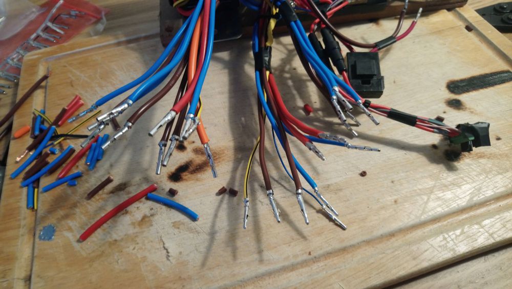
This is it all terminated and ready to go:-
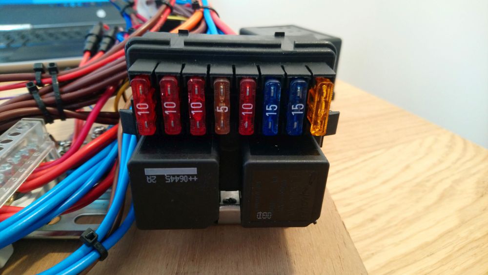
Here is a top view of the fuse & relay box with the lid removed, showing the fuses and relays in place:-
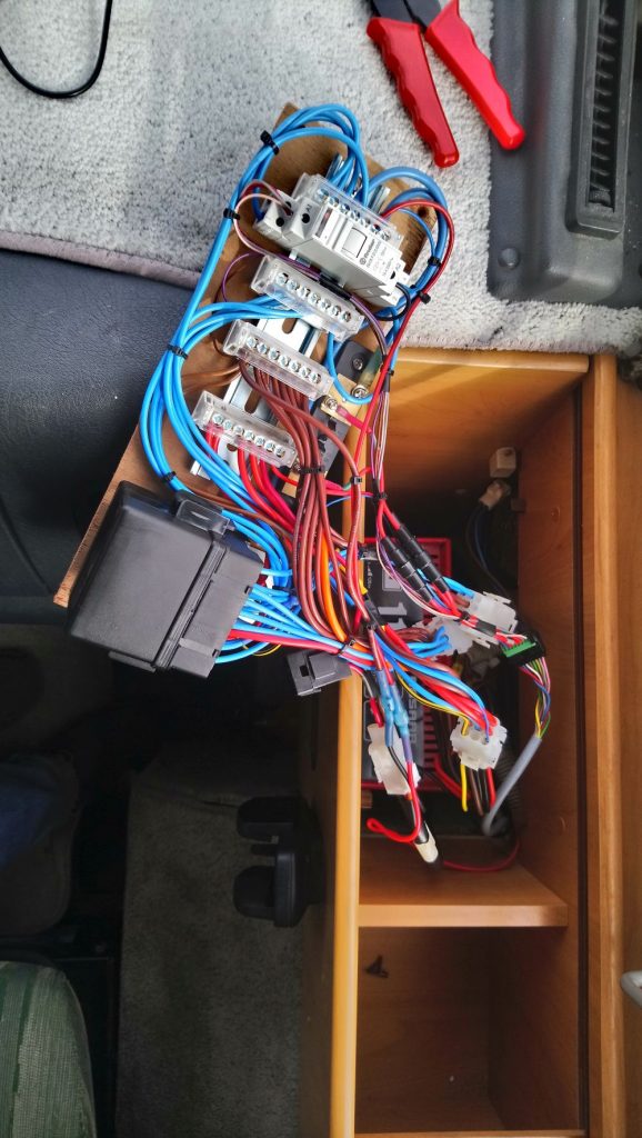
Here is the new system connected to the wiring in the motorhome and ready for final installation
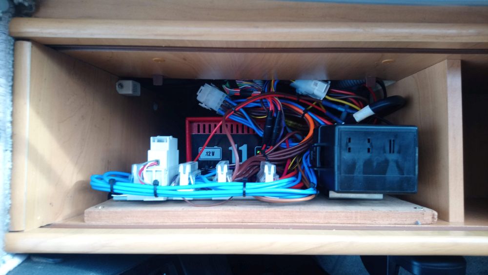
And the final installation inside the original Elektroblock cupboard:-
The new system works perfectly, with the added bonus that the solar regulator can now charge both the starter and habitation batteries.
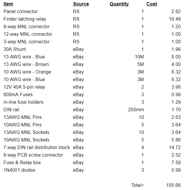
In case you want to create something similar yourself, here is a bill of materials – total cost £105.66 (note – the piece of wood and a few small lengths of different colour wire are from stock I had lying around, so aren’t included in the BoM, I also haven’t included the charger in the BoM as you can pretty much use any charger you like as long as it is designed to be permanently connected to a battery – I ended up using a CTEK unit)
I’m pleased with the outcome and it’s a saving of many hundreds of pounds over a new Elektroblock! Let me know what you think – is it a good idea?, have I missed anything? Also, let me know if you want a copy of the schematic – I’m happy to share it.
Thanks for reading!
Found this information useful? – Want to support Motor-Roam?
Click here to find out how!

September 23, 2019 at 9:51 am
Great article! I am going to do my second VW Transporter DIY conversion and I am looking for inspiration how to do simple “elektroblock”.
September 24, 2019 at 11:57 am
Hi PetrS – thanks for the feedback!, glad the information was useful! Cheers, Dan
December 13, 2019 at 11:59 pm
Classic example of superb DIY reverse engineering! EBLs, which came into use around 95 in Hymer and other motorhomes, while being of decent quality, also introduced a single point of failure, compared with the earlier systems which used separate components. I have seen many an online post detailing the angst caused by a faulty EBL.
For those who don’t fancy a job like this, EBLs can be repaired quite quickly in the UK by two specialist companies – Apuljack Engineering, and A & N Caravan services – both on google and I am not connected to either, just an enthusiastic van owner.
February 23, 2020 at 11:05 pm
Hi
Many thanks for this article, I’m planning something similar so it’s been very useful. I have a couple of quick questions if you don’t mind?
1. What sort of diode did you use between the D+ in and the split charge and fridge relays?
2. Do you have any more details about the connector for the panel? I’ve had a look around but can’t seem to find a suitable one, do you have a link to the one on RS by any chance?
3. With the shunt fitted as it is, does it show on the ammeter on the panel how much the battery is charging and discharging?
Thank you again for the article
Tom
February 24, 2020 at 5:17 pm
Hi Tom!
1) Diodes are all 1N4001 – it’s a common diode made by lots of different manufacturers, easily available from eBay, RS components etc.
2) The panel connector I used is RS part number 737-8587, you should be able to find it here:- linky
3) The shunt is fitted in the same way as it is in the original Elektroblock, so the ammeter in the panel reads correctly for both charging and discharging. You just need to make sure you select a shunt that has the correct mv/A rating – a shunt of the wrong spec will cause it to read either high or low.
Hope this helps!, let us know how you get on and if you have any more questions just ask 🙂
Cheers, Dan
February 26, 2020 at 5:18 pm
Hi Dan
Thanks for teh speedy reply ?. I have got a few more questions if you don’t mind?
1. How did you wire the diode into the D+ wire?
2. Do you know what mv/A rating is needed for the shunt?
I’m just trying to finalise the parts I need then hopefully can get it all wired up next week.
Thanks, Tom
February 26, 2020 at 8:52 pm
Hi Tom – no worries 🙂
1) The D+ diode was just soldered in-line with the wire, with heatshrink over it to protect/insulate it
2) I ended up experimenting to find the right shunt rating, but unfortunately I can’t remember exactly which one I ended up using! They were all 75mV FL-2 shunts bought for a couple of pounds each off e-bay, but in different ranges. I think I ended up with either a 40A (so 1.875mV/A) or a 50A (so 1.5mV/A) shunt.
Good luck with the project! 🙂 Cheers, Dan
March 23, 2020 at 6:00 pm
Hi Dan
Inspiring article, especially now that i am looking for a solution for the problem i currently have. An annoying buzzing sound in the trafo of the Schaudt.
What kind of CTEK did you use in the end and would it be possible to leave the schaud in tact only replacing the internal charger with an external one?
The unit is almost simular to yours it is a ebl4-106
Rgrds Patrick
March 24, 2020 at 4:09 pm
Hi Patrick – thanks for the comment. I used a CTEK MXS-10. It should be easy enough to leave the elektroblock intact and just bypass the internal charger, just look for where the low voltage side of the internal charger connects to the circuit board and connect the CTEK into this point instead. Hope this helps, let us know how you get on! Cheers, Dan
February 26, 2021 at 6:58 am
Hi Dan I bought a motor home with EBL 4-105 missing your EBL 4-105 replacement look great and would solve a big problem for me but I do not have a electric no how to take that on is there anybody you no would Biuld me a replacement like one in this article thank from a very stuck ken allen
February 28, 2021 at 5:43 pm
Hi Ken – thanks for the comment! I’m afraid I don’t know anyone who would build this from plan for you – do you have a technical college or similar near to you?, if you can find one that does electronics or auto electrical courses there are likely to be students there willing to do something like this in their spare time for a few beer tokens!
Otherwise it’s probably worth giving someone like Apuljack engineering a call – they may have a repaired second hand unit kicking about for a good price. Cheers, Dan
May 12, 2021 at 10:54 am
Hello, came across this article and have read it with interest. Although no problems with my 4-105 yet, I do have an issue with the now antiquated (1998) charger. Also I have replaced the leisure batteries with AGM batteries and have read they need a different charging voltage or manner of charging. The charger in your article would achieve this, but the charge coming from the alternator would not get close.(75pc). Thus a battery to battery charger might be a better alternative, but can this be connected to the existing split charging relay or?? I would be interested in your suggestion, thanks Rudy
May 12, 2021 at 9:04 pm
Hi Rudy – it’s worth checking your Elektroblock as they often have a small switch to select between flooded and gel-type batteries (the switch alters the charging regime as you mention). If you are finding the standard split-charge system is not performing for you then you could install a battery to battery charger, I see no reason why you couldn’t connect it to the output of an existing split charge relay (do you have a separate split-charge relay, as opposed to the one inside the elektroblock?) – however I suspect a lot of people talk themselves into needing/wanting a battery to battery charger, rather then actually needing one! Cheers, Dan
May 19, 2021 at 12:42 pm
Hello Dan, thanks for you quick replay, as said my EBL is a 4-105 and does not have a switch, so will replace the original charges with the one you suggested as that one is clever enough to charge anything currently on the marker (GEL, AGM etc), I have read that staying with the current setup will shorten battery life as the charge can only go up to 14.4 volt whereas the currently installed batteries really require 14.8 volt and I believe a different charging curve.
This bypass is thanks to you description not too drastic, but problem remains that whilst driving the leisure batteries will never get to 100% (hence my battery to battery question).
One more question if I may, what made you change all the individual gubbings as opposed to leaving the basics of the EBL as they were?
Thanks
May 19, 2021 at 9:52 pm
Hi Rudy – as it wasn’t clear where the fault with my Elektroblock was it was easier to replace the whole thing than to try and replace just certain buts of it – it was a fun project anyway 🙂
August 21, 2021 at 2:04 pm
Hi Dan.
OThank you for publishing your article – but oooohhh, how I wish I’d seen it a year ago!!
I discovered a big problem with my Schaudt EBL 264, centred around the fridge 12 volt control systems having been shorted out in former ownership and a none too professional job made of getting round it. In effect I rebuilt an external ‘mimic’ of the 12 volt control system (with a good deal of wonderful help and advice from ‘elsewhere’) but it was a lot less than straightforward, especially in view of the very low D+ output available from the alternator.
Either way, your route of completely replacing the EBL would probably have been less work!
Since I’m still less than convinced of the reliability of the rest of the EBL internals – evidence of burnt and bridged PCB tracks – I would be very grateful for a copy of your schematic. If time allows, I’ll probably do the same as you, just for the added confidence in the system.
A question – or two:
1. My Schaudt control panel, whilst different, is in essence the same principle. Is there a way of measuring the existing EBL shunt to replicate it without too much experimentation?
2. Some of the original mate’n’lock connectors were destroyed when the system was damaged. I replaced the necessary but was never too enamoured with the size and robustness of them, especially considering the current the might be required to carry. I know it would mean re-terminating quite a lot of cables but would you see any merit in replacing them with something like properly crimped ring terminals on a screw/bolt post terminal block?
Will
August 24, 2021 at 9:37 pm
Hi Will – thanks for getting in touch! I will send you a copy of the schematic to your e-mail address :). You could measure the existing shunt by using a constant-current power supply to put say 10A through the shunt then measure the output in mV (or use a constant voltage power supply and a known load (such as a power resitor) to give you a known current, then measure the output as before). The mV output should be linear and zero-crossing with respect to current, but you could always measure at a few different current levels for completeness. Replacing the mate’n’lock connectors with ring terminals would be robust but is likely to be very bulky? You could always re-terminate with a ‘better’ connector family if you wanted – Deutsch connectors have a good reputation and are readily available. Let us know how you get on! Hope this helps, cheers, Dan
September 3, 2021 at 3:52 pm
Hi Dan ,
Great article ! Would it be possible to send a copy of the schematic please ?
Thanks
Dan
September 6, 2021 at 8:38 pm
Hi Dan – thanks for getting in touch, schematic sent to your e-mail address 🙂 Cheers, Dan
June 28, 2022 at 3:57 pm
Hi Dan
Same as above, could i get a copy of the schematic please.
I have the EBL 4-105 and the 12v supply to the fridge whilst driving is becoming problematic so maybe something to consider in the future
June 29, 2022 at 7:05 pm
Hi Garrick – no problem, schematic on it’s way to your e-mail 🙂 Cheers, Dan
July 14, 2022 at 6:22 pm
Hi Dan,
My EBL 100-2 has started giving me fairly frequent problems (I think) in spite of a recent repair. I already bypassed the solar and mains charging side and heating and water systems had already been changed by previous owner so a lot of the EBL is redundant but i want to keep the function for the DT100 control panel. Mainly tank levels and inside/outside temperatures.
There is also a Toptron EL155 hidden up behind the control panel that consists of a couple of soldered in relays and circuit board. The step relay has already packed up and this unit is obsolete so will be wired out at some point.
Latest problem is power for my compressor fridge. I am not sure I need a relay for the fridge as the cable is very chunky and I only want it running from my habitation battery . The original 3 way was replaced by a Waeco 110ltr compressor fridge that works well usually. It is power hungry but I have everything in place now to keep be running all year round.
Would you send me a copy of your schematics so I can see if I can adapt it to what I want to try please?
Many thanks
Neil
July 14, 2022 at 11:11 pm
Hi Neil – I’ll send a copy of the schematic to your e-mail :). The purpose of the fridge relay is to only power the fridge from 12V when the engine is running – if you have a compressor fridge and plan to run it permanently from the leisure battery then the fridge relay shouldn’t be needed – you will need to control the fridge some other way though, or just turn it off when you don’t need it.
Regarding the Toptron unit – if it is just a failed soldered-in relay I would be very surprised if they haven’t used standard ‘off the shelf’ relays, you should be able to find something of the same spec and form-factor and solder it in place of the original relay (I use RS.com for this sort of stuff) Hope this helps, Cheers, Dan
July 15, 2022 at 12:00 pm
Email received, thanks Dan 👍
August 24, 2022 at 7:21 pm
Thank you for a very good article. Could you be so kind sending me the schematic? My Elektroblock 4-105 is not working anymore.
Thanks from Norway 🙂
August 24, 2022 at 9:44 pm
Hi Torgeir – thanks for the message, I’ve sent a copy of the schematic to your e-mail 🙂
Cheers, Dan
November 5, 2022 at 5:18 pm
Cracking article. Thanks for the information. A detailed schematic would be most useful to help guide a re-wire of our newly acquired 2004 Hymer B524 with EBL 100. Keep up the good work!
November 6, 2022 at 3:29 pm
Hi Alistair, thanks for the comment, I’ve sent you a copy of the schematic to your e-mail address 🙂 Good luck with the project! Cheers, Dan
January 29, 2023 at 10:12 am
Hi Dan. Thank you for the article. I would like to see the schematic too, please. Our (old) electroblocks hook-up charger is not working, and for a start I will replace it with a CTEK charger, but I consider replace the whole thing soon. Thank you, and greetings from Denmark 🙂
January 29, 2023 at 10:52 am
Hi Thomas – thanks for the comment, I’ve e-mailed you a copy of the schematic – good luck with you project 🙂 Cheers, Dan
May 17, 2023 at 12:35 pm
Hi Dan ,
SuperB article! Planning to do similar to my ’14 Movano project. I will put 2no 1495*685 180W each solar panels, and 2no 100ah batteries. Would it be possible to send a schematic please ?
Thanks
Lucas
May 17, 2023 at 2:30 pm
Hi Lucas – thanks for the comment! No problem – I’ve sent a copy of the schematic to your email Cheers, Dan
August 27, 2023 at 9:18 pm
HI Dan
Thanks so much for your support in sharing this information. Please send the schematics as our EBL 101 is not working in our Hymer and we have same problem with 12v fridge not running whilst driving. Thanks from Australia -Carron
August 28, 2023 at 4:16 pm
Hi Carron, thanks for the message – copy of the schematic has been sent to your e-mail address 🙂 Cheers, Dan
September 21, 2023 at 10:16 pm
Great article and well done.
Is it possible to send me a copy of the schematic.
I’m having problems with my ebl 99.
Thanks
September 21, 2023 at 10:40 pm
Hi Guy – thanks for the comment – a copy of the schematic should be in your email inbox now 🙂 Cheers, Dan
December 8, 2023 at 7:26 am
Great project. I’m designing my own EBL with integrated CPU and some cool stuff. So far I’m thinking spade terminals, cheap and can be tight packed. But MNL sockets to be plug-in compatible with my EBL-99 would be nice.
Do you have the exact product numbers for the connectors you used? It’s a messy place with lots of versions out there.
Thanks.
https://oshwlab.com/matsekberg/ebl-666
December 8, 2023 at 12:39 pm
Hi Mats! Looks like fun – good luck with the project! I’m afraid I lost my bill-of-materials years ago but if I can dig anything up I’ll post it on here 🙂 Cheers, Dan
December 18, 2023 at 12:06 pm
Great article and well done.
Is it possible to send me a copy of the schematic.
I’m having problems with my ebl 99.
Thanks
December 18, 2023 at 4:49 pm
Hi John – thanks for the comment, schematic should be in your inbox now 🙂 Cheers, Dan
February 8, 2024 at 5:50 pm
hi dan my friends ebl 208 is not repairable could you please send me a copy of the schematic it looks a perfect replacement.
cheers
mick
February 9, 2024 at 10:18 am
Hi Mick – thanks for getting in touch, the schematic should be in your inbox now! Cheers, Dan
June 15, 2024 at 10:09 pm
Hi Dan I have the electroblock in my Avan Motorhome and I’m thinking about adding lithium batteries and just disconnecting the battery charger from the mains PowerPoint and adding a lithium profile charger do you think that might work for me? Also could you please send me a copy of your system to my email much appreciated.
June 16, 2024 at 10:08 pm
Hi Barry – yep, I don’t see any reason why that wouldn’t work, you would just need to look at how you feed power from the lithium charger into the system if you want the current display to correctly show charging current (assuming you have a battery current display fed from the shunt in the Elektroblock in your motorhome?). Anyway, good luck with the project, I’ll send you a copy of the schematic now! Cheers, Dan
August 13, 2024 at 10:16 am
Hi Dan,
Thank you for this great article! We recently bought a Hymer with a Schaudt EBL 4-105.
Unfortunately the fridge does not work on 12 V. Also the stairs an some others are not working. This leads me to the conclusion that block 4 on the EBL is failing. So I have 3 options, repair, replace or build my own. I would love to have a look at the schematics of your design. Is the BOM you listed at the start of the article in line with the schematics?
August 13, 2024 at 3:28 pm
Hi Leon – thanks for the comment, I’ve sent a copy of the schematic to your email address 🙂 The BoM in the article should line up with the schematic, cheers, Dan
August 15, 2024 at 12:34 pm
Hi Dan,
I am sorry to tell you I have not received any email from you yet. Can you check? Just in case, this is my phone number so Whatsapp should work too, +31 622500852
Thank you.
August 15, 2024 at 12:55 pm
Hi Leon – apologies, I just checked and I had mispelled your e-mail address! I have just forwarded it to the correct address, hopefully it should work this time 👍 Cheers, Dan
November 21, 2024 at 3:33 pm
Hi Dan,
Just came across your post after my EBL charger has stopped charging the leisure battery whilst on mains (but still charges from the engine ok). I’m looking into a diy repair so your schematic would be very helpful.
Thanks in advance.
Brian
November 21, 2024 at 5:13 pm
Hi Brian – schematic should be in your inbox now! 👍 Good luck with the project, let us know how you get on! Cheers, Dan
February 27, 2025 at 3:49 pm
Hi Dan great new design thanks,
I am wishing to upgrade my EBl 99 to run lithium cab battery , I purchased a dc to dc convertor and integrated mppt any idea how I might integrate into my system , happy to pay for any assistance
Regards
Sean
February 28, 2025 at 11:53 am
Hi Sean – thanks for the comment. If you unplug the mains power feed from your EBL99 you will disable the charger functionality without affecting the rest of the EBL (everything else will continue to work normally). You can then connect the DC/DC to your Lithium battery wherever is convenient (paying attention to fuse protection, wire sizing etc. obviously). Hope this helps! Cheers, Dan
January 8, 2025 at 10:27 pm
Hi Dan, i have problems on my ebl 104, can you send the scheme PLS? Nice work 👏 and thanks
January 9, 2025 at 11:01 am
Hi Hugo – schematic should be in your inbox now 👍Good luck and let us know how you get on! Cheers, Dan
October 30, 2025 at 3:12 pm
Hello. We have a damaged electroblock 105 in our Hymer s660. We are looking at doing what youve done and a schematic would be very helpful. Please email us at thenels@aol.com.
Thank you.
October 30, 2025 at 6:46 pm
Hi Michele, schematic should be in your inbox now 👍Cheers, Dan
January 12, 2026 at 7:22 pm
Hi Dan, I have a faulty EBL 101 that I need to replace as there is no one competent in New Zealand to repair it. I would really appreciate a copy of your schematic as your approach seems the best option.
January 16, 2026 at 1:58 pm
Hi Robbie, thanks for the message – the schematic should be in your inbox now! Let us know how you get on, it would be great to see some pictures of your implementation if you decide to go down this route……. Cheers, Dan